Description
Test Interfaces
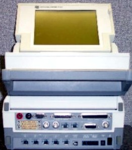
34 pin V.35 Interface
25 pin RS-232C/Mil-188C Test Interface
37 pin RS-449/422/423 Test Interface
9 pin RS-232C Interface for Serial Printing and Remote Control
Dual Bantam and RJ-48 T1/E1 Interface Jacks
15 pin T1/E1 Interface
BNC Jack for T1/E1 Clock Input, ISDN Clock input and External BERT Clocking
RJ-48 jack for use by the speaker monitor input and for tone generator signal injection input/output
Handset Jack for Voice Communications
ISDN (S/T & U) Interface Jacks
Protocol Analysis Options
PPP, Frame Relay, SNA, X.21, X.25, Baudot, DDCMP, ISDN (Q.921/Q.931), LAPD X.25, SS7/SS#7/IS-41
T1 / 2.048 MHz / CEPT / E1 Transmission Tests
US Standard T1-1.544 Mbps
CCITT Standard 2.048 Mbps
Dual T1/E1 Receivers and Transmitters
Clocking: Recovered, External, Internal
Selectable Line Buildout: O dB, -7.5 dB, -15 dB
Automatic Line Buildout: O to -37 dB
Selectable Line Equalization: 0-133 Feet, 133-266 Feet, 266-399 Feet, 399-533 Feet, 533-655 Feet
Line Codes: AMI, HDB3, B8ZS, B7 and Auto Configure
Framing: Unframed, D1D, D2, D3, D4, ESF, CEPT 2M (E1), Framed 2M , Multiframed, and Auto Configure
Line Terminations: Terminated (US 100 ohms, G.703 at 75 ohms or 120 ohms), Bridged ( 1000 ohms), Drop/Insert Terminated, Drop/Insert Bridged
BERT Test Patterns: Mark, Space, 1:1 (Alt), 1:3, 1:7, 2:8. Yellow Alarms, Blue Alarms, Red Multi-frame Alarms, 3:24, 63, 511, 2047, QRSS, 2^15-1, 2^20-1, 2^23-1, 2^23-1 with 14 Zero Suppression, 24 bit User Defined Pattern
CSU Loop Up/Loop Down commands, Smart Jack Loop Up/Loop Down commands
Time stamped Error Reporting to Disk and/or Printer
Scripted BERT Testing (User Definable)
Drop and Insert
Drop and Insert to RS-232, RS-449, V.35 Interfaces or Any Protocol Analysis Instrument and BERT
16K BRITE Card Drop to Q.921/Q.931
Channel Display (24 or 32 Channel Display)
24 T1 or 32 E1 Channels Simultaneously Displayed
Hex, Binary, status
Signaling Bit Display
24 Channel T1 or 32 E1 Display of Signaling Bits
Wink Measurements for Response and Duration Times (Intrusive and Monitor Modes)
Time stamped Signal Bit Capture, 1-24 Channels
Digital TIMS
Transmission and Measurement of Voice Range Tones via T1/E1 Drop and Insert
Drop Out for Measurement or Insert to Generate Level and Frequency for Individual T1 Channels or E1 Timeslots
Lead Status Monitor
Graphics Display: Mnemonical for V.35, RS-422, RS-232
Alarms: Visual and Audible – Triggered when Selected Lead(s) go on or off
Baud Rate Frequency Counter on Transmit and Receive Clocks
Data Line Monitor with Auto Configuration
Monitor/Emulate Internal RS-232, V.35, RS-449/422/423 Interfaces
Protocols SDLC, SDLC(NRZI), HDLC, BSC, Async, Programmable Sync (1 or 2 character sync), IPARS
Emulation: DTE and DCE
Data Capture from Drop and Insert, BRI, PRI, T1 and E1
Data Monitor and Emulation Rates: 256 Kbps (400 Kbps aggregate)
Codes Sets: ASCII, EBCDIC, 6-bit Transcode, IPARS, EBCD
Lead Status: Real Time Status Displayed During Data Monitoring
Error Checking: CRC-CCITT, CRC-6, CRC-12, CRC-16, LRC and Parity
High Speed Bit/Block Error Rate Tester
Synchronous and Asynchronous Data
Full Duplex and Half Duplex (Ping Pong) Modes
Half Duplex (Ping Pong) Mode is centralized. NP7000 can control up to 32 Remote NP7000’s.
Interfaces: RS-232, RS-449/422/423, V.35
Receive / Transmit Patterns: 63, 511, 2047, 4095, Mark, Space, and User Programmable Patterns, (63 byte QBF and 24 bit binary), 2^15-1, 2^20-1, 2^23-1, 1:1, 1:3, 1:7, 3:24, QRSS
Data Block Size: CCITT Specifications – 63, 511, 2047, 4095 Bits
DDS Loop Patterns Supported : OCU, CSU, and DSU Loop Backs (Latching, Non-latching, Release) During Tl/E1 Drop & Insert
US Specifications 1000 Bits
Internally Generated Transmit Speeds (bps): 75, 110, 134.5, 150, 200, 300, 600, 1200, 1800, 2000, 2400, 3600, 4800, 7200, 9600, 12000, 14400, 16000, 19200, 28800, 32000, 38400, 48000 Synchronous and Asynchronous, 56000, 57600, 64000, 72000, 128000, 192000, 256000, 384000, 460800, 512000, 576000, 768000, 1024000, 1152000, 1536000, 2048000, External, Synchronous
Clocking DCE Source, DTE Source, External
Character Framing: 5, 6, 7 or 8 Bits, Plus Parity, 1, 1.5, or 2 Stop Bits
Parity: Odd, Even or None
Test Duration: 1, 5, 10, 30 Minutes, Continuous
Lead Status Display
Alarms: Visual and Audible – Conditional Triggering on Bit or Block Error Counts
Single or Block Error Inject
VT220 Terminal Emulator
Programmable function keys (F1-F12) with 20-character answer back message for F1
Code Sets: ASCII of EBCDIC
Character framing: 7 or 8 bits per character width and 1, 1.5 or 2 stop bits
Parity: Odd, Even or None
Remote Control (RS-232C/V.24) Port
Remote unit is controllable from VT220 or PC (Running VT220 Emulation)
Memory
RAM: 1 Mb program data storage
Flash Memory: 1 Mb non-volatile program storage
Data Storage
Floppy Disk: 2Mb 3.5″ diskette with maximum capture buffer size of 600K
Hard Drive: 40Mb with maximum capture buffer size of 16Mb
Power
Removable rechargeable Nickel Cadmium (Ni-Cad) battery. AC adapter included.
Charging time: 3 hours
Operating time on battery: 1-3 hours nominal (Depends on test functions being performed.)
Standard Accessories
Custom Softcase, Cables, User Manual, System Diskette
AC Adapter 120V / 12 VDC, 2.5 Amps, (International) 220V / 12 VDC, 2.5 Amps
Removable Nickel Cadium (Ni-Cad) Battery
Data Display/Keyboard
Size: 2000 Characters (80 x 25) supertwist high contrast LCD with backlight
Keys: 65 Full ASCII Character Set. Unsealed, 10 million keystroke operation life
9.88″ Wide x 4.37″ High x 8.5″ Deep (25.10 cm x 11.10 cm x 21.59 cm)
Weight: (Base Unit) 8.5 Pounds (3.86 kg)
Environmental
Operating Temperature: 10ø C to 50ø C (50ø F to 122ø F)
Operating Humidity: 10% to 80% Relative Humidity Non-condensing
Storage Temperature: -30ø C to 60ø C (-20ø F to 140ø F)
Storage Humidity: 5% to 95% Relative Humidity Non-condensing
Tone/Sweep Generator
Fixed Tone 100 Hz – 20,000 Hz with selectable output levels, One Hz increments
Sweep: On screen 21 point frequency Vs level graphs in four ranges; 300 Hz – 3.6 Khz, 100 Hz – 5Khz, 100 Hz – 10 Khz, 100 Hz – 20 Khz
Receive Accuracy: 100 Hz – 40 Khz +/- 2 dB, 900 Hz – 1025 Hz +/- .3 dB
Transmit Level Range: 0 dBm to -16 dBm =/- 1 dB at 135 ohms
Dual Channel Oscilloscope
Display is automatically updated once per trigger point
Triggering Sources: CH-l, External. Slope: + or – selects the positive or negative excursion of the signal to start the sweep
Modes: NORMAL sweep, SINGLE sweep
Maximum Input Voltage: 40 V p-p normal operation protected to 400 V (DC + AC peak)
Digital Volt/Ohm Meter
Input Impedance: 10 M Ohm
Capture Buffer Sizes: user selectable or dynamic based on available memory
Volts AC: 0-400 V (True RMS), 400 mV (100 Hz – 100 Khz), 4 V (100 Hz – 100 Khz), 40 V (100 Hz – 10 Khz), 400 V (50 Hz – 60 Khz +/- 2%)
Volts DC: -400 V to +400 V +/- 2% dBm: -57 dBm to +54 dBm +/- 2.5%
Ohmmeter: 0 Ohms to 40 Meg Ohms +/- 2.5%
Continuity Thresholds: 50 Ohm, 600 Ohm, 1 K Ohm, 10 K Ohm, 1 M Ohm
Speaker Monitor
Speaker monitor can be used simultaneously with other instruments
Gain: +2dB, +8dB, +14dB, +22dB, +28dB, +34dB


