Description
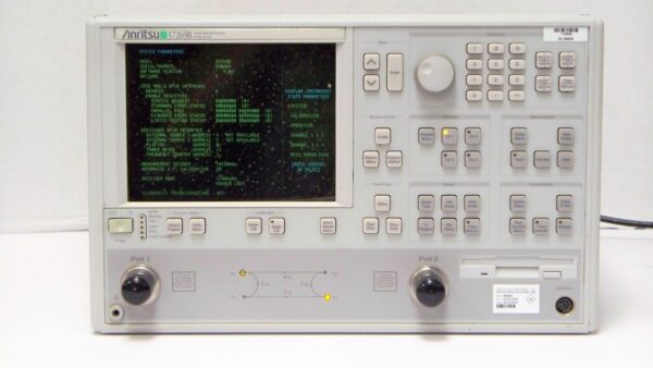
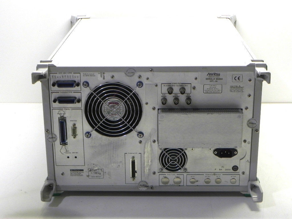
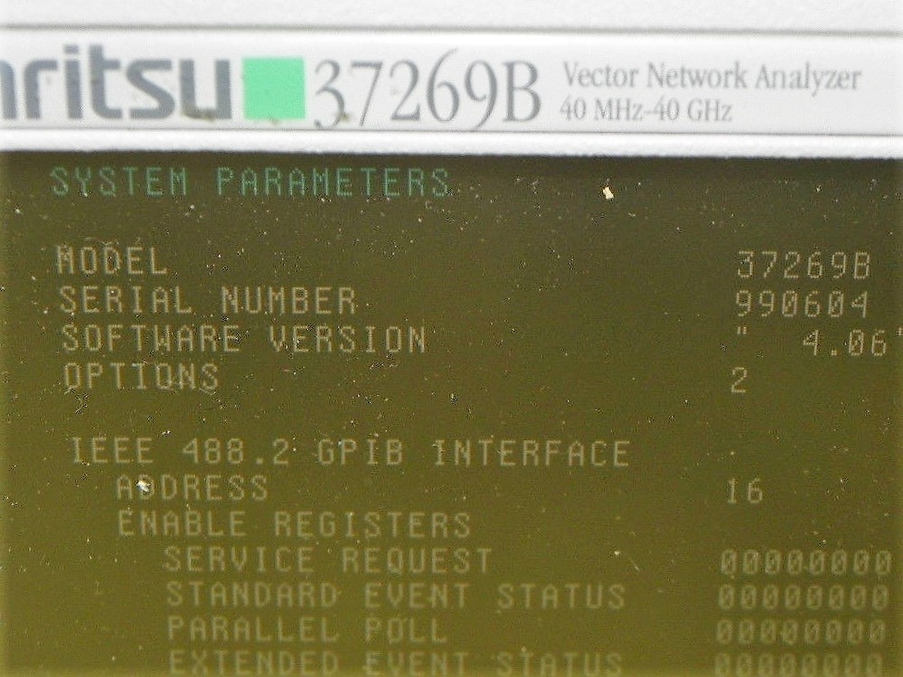
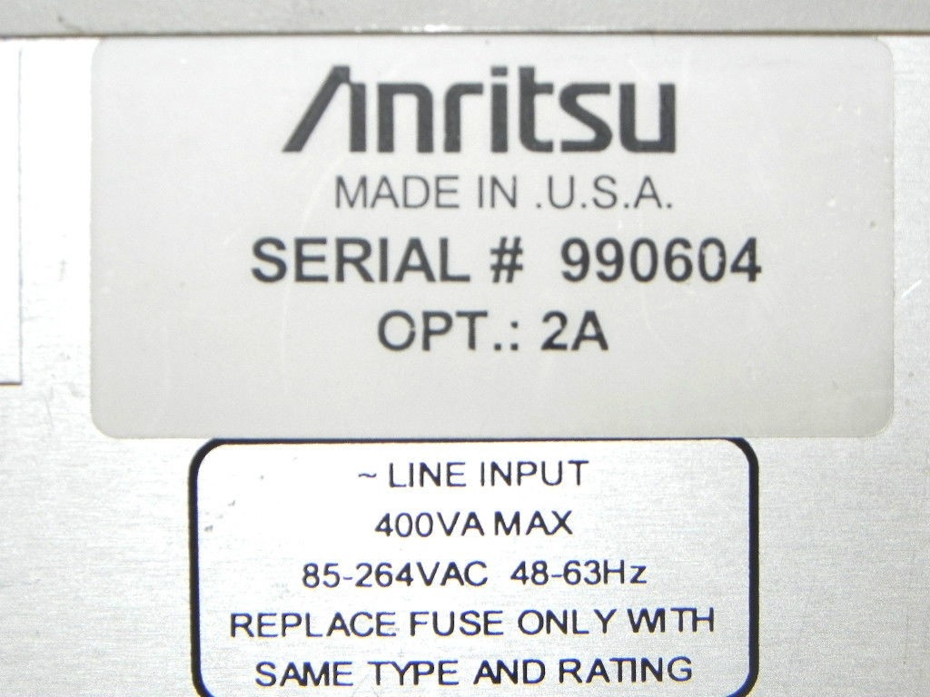
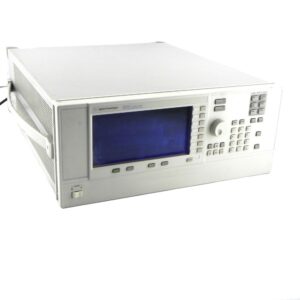
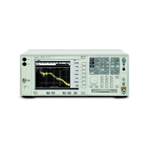
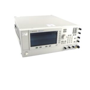
The Anritsu 37269B Vector Network Analyzer is a high performance analyzer designed to make fast and accurate S-parameter measurements of passive devices across the 40 MHz to 40 GHz frequency range. The Anristu 37269B network analyzer integrates a synthesized source, S-parameter test set and tuned receiver into a single compact package that is ideal for bench-top testing.
High throughput measurements are achieved in each model through the use of fast, 12-term error corrected sweeps, fast GPIB data transfers and an intuitive user interface. All measurement results are displayed on a large LCD color display or on an external VGA monitor.
- Features of the Anritsu 37269B Network Analyzer include:
- Fast Sweeping Synthesized Source
- Auto Reversing Test Set
- Solid-State Transfer Switch
- Four Independent Displays
- Four Channel Receiver
- Internal Hard and Floppy Disk Drives
- LRL/LRM Calibration
- Adapter Removal Calibrations
- Fast Measurement Throughput via GPIB
Dynamic Range:
- High Level Noise (typical): <0.03 dB and <0.4 degrees peak-topeak variation in a 1 kHz
- IF bandwidth up to 20 GHz. <0.08 dB and <0.5 degrees peak-to-peak variation up to 40 GHz.
- Measurement Throughput: Measurement times are based on a single 40 MHz to 20 GHz sweep with 10 kHz IF bandwidth (no averages) after a full 12-term calibration. Sweep times include retrace and band switch times.
- Measurement Time (ms) vs. Data Points (typical):
- Calibration Type/Data Points
- 1 Port (3 Term): 3/60 51/250 101/330 401/960 1601/3300
- Full 2 Port: 3/60 51/270 101/400 401/1000 1601/3600
- Calibration Type/Data Points
- Measurement Time vs. Sweep Mode for 101 Data Points (typical)
- Measurement Time vs. IF BW for 101 Data Points (typical)
- Measurement Time vs. Span for 101 Data Points (typical)
Measurement Capabilities of the Anritsu 37269B include:
- Number of Channels: Four independent measurement channels.
- Parameters: S11, S21, S22, S12, or user defined combinations of a1, a2, b1, and b2. All measurements are made without the need to manually reverse the test device.
- Measurement Frequency Range: Frequency range of measurement can be narrowed within the calibration range without recalibration. CW mode permits single frequency measurements, also without recalibration. In addition, the system accepts N discrete frequency points where 2 < N < 1601.
- Domains: Frequency Domain, CW Draw, and optional High Speed Time (Distance) Domain. Formats: Log Magnitude, Phase, Log Magnitude and Phase, Smith Chart (Impedance), Smith Chart (Admittance), Linear Polar, Log Polar, Group Delay, Linear Magnitude, Linear Magnitude and Phase, Real, Imaginary, Real and Imaginary, SWR, Power.
- Data Points: 1601 maximum. Data points can be switched to a value of 801, 401, 201, 101 or 51 points without recalibration (if 1601 points were used in the calibration). In addition, the system accepts an arbitrary set of N discrete data points where: 2 < N < 1601. CW mode permits selection of a single data point without recalibration.
- Reference Delay: Can be entered in time or in distance (when the dielectric constant is entered). Automatic reference delay feature adds the correct electrical length compensation at the push of a button. Software compensation for the electrical length difference between reference and test is always accurate and stable since measurement frequencies are always synthesized. In addition, The system compensates reference phase delay for dispersive transmission media, such as waveguide and microstrip.
- Markers: Six independent markers can be used to read out measurement data. In delta-reference mode, any one marker can be selected as the reference for the other five. Markers can be directed automatically to the minimum or maximum of a data trace.
- Enhanced Markers: Marker search for a level or bandwidth, displaying an active marker for each channel, and discrete or continous (interpolated) markers.
- Marker Sweep: Sweeps upward in frequency between any two markers. Recalibration is not required during the marker sweep.
- Limit Lines: Either single or segmented limit lines can be displayed. Two limit lines are available for each trace.
- Single Limit Readouts: Interpolation algorithm determines the exact intersection frequencies of test data and limit lines.
- Segmented Limits: A total of 20 segments (10 upper and 10 lower) can be generated per data trace. Complete segmented traces can be offset in both frequency and amplitude.
- Test Limits: Both single and segmented limits can be used for PASS/FAIL testing. The active channel’s PASS or FAIL status is indicated on CRT after each sweep. In addition, PASS/FAIL status is output through the rear panel I/O connector as selectable TTL levels (PASS=0V, FAIL=+5V or PASS=+5V, FAIL=0V).
- Tune Mode: Tune Mode optimizes sweep speed in tuning applications by updating forward S-parameters more frequently than reverse ones. This mode allows the user to select the ratio of forward sweeps to reverse sweeps after a full 12-term calibration. The ratio of forward sweeps to reverse sweeps can be set anywhere between 1:1 to 10,000:1.
AccessoriesOptions
| Frequency | Max. Signal Into Port 2 (dBm) | Noise Floor dBm | Receiver Dynamic Range (dB) | Port 1 Power (dBm, Typical) | System Dynamic Range (dB) |
| .04 | +20 | -70 | 90 | 0 | 70 |
| 2 | +3 | -98 | 101 | 0 | 98 |
| 20 | +3 | -95 | 98 | -5 | 90 |
| 40 | +3 | -93 | 96 | -15 | 78 |
| Sweep Mode | Time (ms) | ||||
| Linear | 350 | ||||
| List | 350 | ||||
| CW | 230 | ||||
| IF Bandwidth | Time (ms) | ||||
| 10 kHz | 350 | ||||
| 1 kHz | 530 | ||||
| 100 kHz | 1900 | ||||
| 10 Hz | 14000 | ||||
| Frequency Span | Time (ms) | ||||
| 40 MHz to 40 GHz | 500 | ||||
| 20 GHz to 40 GHz | 400 | ||||
| 10 GHz to 11 GHz | 250 | ||||
| Option | Description | ||||
| 1 | Rack Mount | ||||
| 2 | High Speed Time Domain Capability | ||||
| 4 | External SCSI-2 Hard Drive Compatibility (Internal HDD Removed) | ||||
| 7A | Universal GPC-7 Connector | ||||
| 7N | N-Type (male) Connector | ||||
| 7NF | N-Type (female) Connector | ||||
| 7S | 3.5mm Connector | ||||
| 10A | High Stability Ovenized Timebase (1 Hz Resolution) | ||||
| 11 | Reference Loop Extension Cables |
